- Contact Person : Mr. Chen Kurt
- Company Name : Xiamen Csumtech Electro-Mechanical Equipment Co., Ltd.
- Tel : 86-592-5732562
- Fax : 86-592-5732960
- Address : Fujian,Xiamen,Room 703A, Chuangye Building, Pioneering Park in Hi-tech Innovation Center, Xiamen
- Country/Region : China
- Zip : 361009
Multi-workstations Flexible line of Motion Control System
I. Brief for the applications:
1. Application demand:
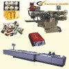
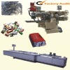
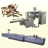
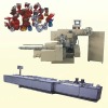
Showed as the above pictures, during the process such as continuous manufacturing, assembly, material distribution, extrusion and molding, usually the servo or step motor are widely used for the works such as accurate location, quantitative control, precise installation and so on. So it is important to setup a flexible, stable and powerful system focused on multi-axis servo and step motor control, and this is the common requirements of such similar applications.
2. Constitute of the system:
In these applications, the work units based on multi-axis servo and step motors are:
1). Motion unit: usually as the X-Y-Z coordinates robotic arms, which completes an accurate motion location and cooperate with the execution unit to finish the technological requirements.
2). Execution unit: composed mainly by the drivers as servo or step motors, to complete the exact production technology such as auto material charge/discharge, auto extrusion, assembly and so on.
3). Other accessory units:
The mainly common units are ordinary motor driver unit, sensor unit, temperature control unit, electric/pneumatic actuating unit etc. All these units can make detection and control by communication ways, they are serve as accessory units for the core unit of servo or step motion control units.
3. System constitute and control requirement list:
II. Solutions:
1. The main hardware
2. Description for functions of software system:
1). Man-machine interaction:
Input, edit and save the motion trails. Support the image elements such as point, line, 3 points circular arc, fold line, multipoint curve, special function (user-defined). The input way is lead-through teaching.
2). Data processing:
Programming the motion trail according to the input picture, finish the interpolation calculation and save data.
3). Built-in driver:
The port and driver for pulse output and motor’s driver are built in the software, and the
input & output for position detection, logic processing (position limit signal, operational signal etc.) are also included in.
4). Backup the data:
Can backup the input data through the USB port copy.
5). User’s interface:
User can interchange the data with any PLC through the way of I/O link, and finish the control functions that is user-defined . Ports of 5I/1O are necessary for the user’s PLC and using the open protocol.
6). Multi-workstations link by I/O:
Linked by I/O communication for multi-workstations, such as the unified tatk time, emergency stop by alarm etc.
III. Interfaces show for touch screen software:
IV. Advantages of the system:
1).Modular and flexible structure: all the workstations are the independent control system, each can run independently or combine and link to run in a line, good properties for extending and maintenance .
2).Graphical program without code:
Programming with the teaching, and make it playback to run the system, which can plan for the freewill motion track, so this is simple, easy and flexible, with the suffering for code programming.
3). Whole system transportability:
Since all the hardware and software are designed by modular idea, which makes the system having the good transportability. Specific to different customer and their different applications,, users’ engineers can use the setup the good practical customized system based on the same hardware and software platform in a very short time.
V. Example for system setup:
1).Diagram for the system design:
The below picture is the schematic diagram for LED assembly line. There are altogether 13 workstations in this line, and 16 sets of coordinates robotic arms are installed to complete all the assembly jobs.
2). Setup list for the system:
VI. Application cases:
1). LED lamps assembly line:
2). Sanitary wares assembly line
3). Auto material charge/discharge of machine tool:
4). Food depositing and molding production line:
5). Auto spray painting with robotic arm: 5). Auto spray painting with robotic arm:
Multi-workstations Flexible line of Motion Control System


